Surface hardening steel produces a volume increase in the hardened section relative to adjacent unhardened sections.
This induces stresses and may result in distortion or cracking in poorly designed components. A satisfactory outcome relies on sound design and the correct choice of material and hardening method.
Flame and induction hardening have significant advantages over heat treatment methods involving through hardening because only the specific area requiring hardening is affected – general problems of distortion are minimized and design restrictions apply only to the heat-affected zone.
Designing for flame or induction hardening is similar to designing for other heat treatment processes. The ideal shape is one where heat is absorbed (during the heating cycle) and transmitted (during the quenching cycle) at the same rate across the entire surface being hardened. This may be difficult to achieve in practice but these simple guidelines may help (these apply only in the heat affected zone).
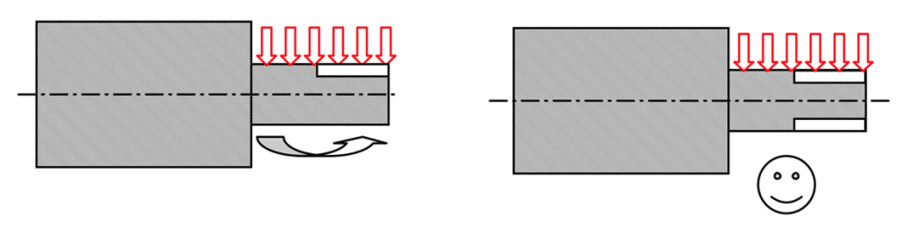
- Avoid large differences in section thickness.

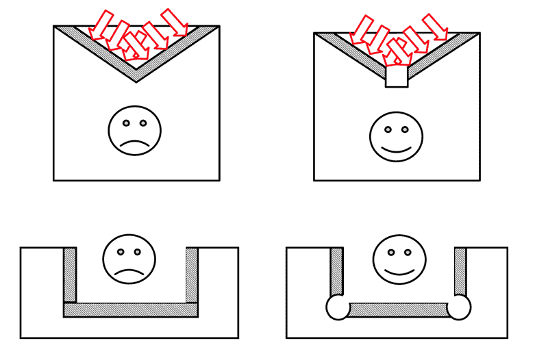
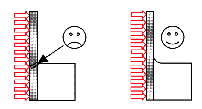
- Avoid sharp corners that may create notch effects – use fillet radii and chamfer holes.

- Keep the shape simple, uniform and symmetrical.
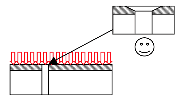
- Do not place holes too close to the hardened surface (about 20mm min) – drill after hardening if in doubt.
- Allow for grinding or final machining of bores in components where the bore is large relative to the OD.
It is always advisable, when making large batches, to produce, harden and test a small sample batches.
Grinding allowance
Many components such as track wheels, gears, sprockets and tie-bars are satisfactory in the as-hardened condition. For components, such as bearing journals, where precision is important you may need to leave a grinding allowance of 5-20 thou (125-500 micron) depending on diameter. If there are large quantities involved we can always run a sample for you to check.
Hardness
The hardness obtained will depend on the exact material composition (there are differences in composition between batches material of the same specification) and the particular flame hardening process used. Typically 1045 and 4140 give hardness levels of 45-58 HRC. Unless there are specific reasons for doing otherwise it is best to specify a hardness range within the normal range for the material concerned. While specific hardness levels can be obtained by tempering back this involves an additional process, more time and higher cost.
Case Depth
This depends on the hardenability of the material, the section thickness and the flame hardening process used. Typically plain carbon steels give case depths of 1-3 mm and alloy steels 3-12 mm depending on the process.
Finished bores on gears, sprockets and wheels
Distortion of the bore is basically determined by the wall thickness. When the bore is large relative to the outside diameter (thin wall) the bore is more likely to move. Thus the bores of small diameter components with relatively large bores are more likely to move than large diameter components with relatively small bores.
Straightness of shafts
Always allow for straightening particularly on small diameter shafts. The effect of flame hardening on straightness is unpredictable but decreases as the length to diameter ratio decreases. If a shaft distorts too much during the hardening process it may be necessary to stop the process and straighten it before proceeding.
To reduce the risk of bending or distortion it is good practice to rough machine, stress relieve and then final machine (leaving a grinding allowance if required) and finally harden.
If shaft journal run out is critical mill two keyways diagonally opposite to minimise distortion.
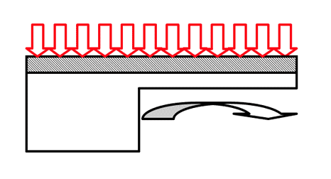
Straightness of strips
Flame hardening the edge of a steel strip will invariably cause it to bend and induces a permanent set in the material. Supplying thin strips attached to a backing bar will reduce this problem.
Section changes and holes in the heat affected zone
Section changes or holes in or near the area being flame hardened generate “hot spots” during the heating cycle and “cold spots” during the quenching cycle. This significantly increases the risk of quench cracking in or around these areas. While less heat input reduces the problem this may result in low hardness levels in the hardened zone. If it is necessary to have a hole in the hardened zone, for example a lubrication hole, always chamfer the hole to remove the sharp edge.
Wheel treads and ways
Separating adjacent hardened zones in wheels & ways reduces flame interference and gives a more uniform hardened layer.